In en-route flight management and planning, Top of Descent (T/D) is the calculated point during a flight in which the aircraft begins descent for the arrival airport. Top of Descent (T/D) can be calculated either manually or automatically.
On modern commercial aircraft, T/D calculations are performed automatically by the Flight Management System (FMS).
How is Top of Descent (T/D) Calculated on Commercial Aircraft?
T/D is determined automatically as part of the Vertical Navigation (VNAV) function found on modern autopilot systems. With this system, the autopilot computers determine T/D by taking the following factors into account:
- The aircraft’s cruise altitude
- Altitude and Speed constraints on the arrival route
- Vertical Speed (feet per minute) limitations – in order to provide optimal descent rate in relation to passenger comfort and design limits, the autopilot system ensures feet per minute (f/pm) parameters are kept within limits for the descent.
- Target altitude – when an aircraft leaves its cruise altitude and begins the initial descent, a target altitude will be selected on the altitude window of the respective autopilot system. Initial target altitude can vary based on ATC instructions and arrival routes.
Also Read: Inertial Navigation System (INS) and Inertial Reference System (IRS) – Differences and Functions
Top of Descent (T/D) on Airbus and Boeing Aircraft
Top of Descent (T/D) management will vary based on aircraft type. Taking the 2 major aircraft manufacturers into account, there are subtle differences in T/D management and initiation.
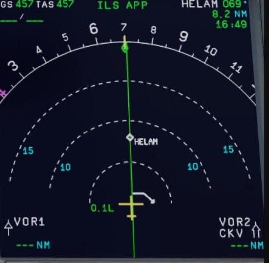
On both manufacturer types, however, Top of Descent (T/D) is clearly marked on the Navigation Display and also via the Descent and Flight Plan pages on the FMS.
On the Primary Flight Display (PFD) of aircraft, there is a visual prompt issued at T/D, which will consist of a message such as DECELERATE; in which aircraft thrust should be adjusted to descent power.
Descent thrust settings are controlled by the auto thrust/autothrottle system, which forms part of the autopilot system.
In Airbus aircraft, pilots must activate descent mode (managed or open mode) at T/D by pushing or pulling the altitude knob with the pre-selected target altitude. The aircraft will then begin its descent on autopilot.
The process on Boeing aircraft is slightly more automated, with T/D being automatically initiated once the target altitude has been set on the autopilot panel.
For safety reasons and under Reduced Vertical Separation Minima (RVSM) procedures*, initial descent should be initiated and conducted via the autopilot system of the aircraft.
The vertical deviation parameter is an indication found on both aircraft types which provides an indication in regard to the aircraft’s position vertically in relation to the correct descent profile.
Vertical Deviation indications are given on the bottom right of the Navigation Display (Boeing aircraft) and on the PFD (Airbus aircraft).
*RVSM is only applicable when operating at FL290 or above
How to Calculate Top of Descent (T/D)
Outside of commercial operations, in General Aviation for example, T/D is usually calculated manually by the pilots. A simple rule of thumb exists that assists in calculating the distance (Nautical Miles) needed for the descent.
This rule of thumb is Current Altitude – Target Altitude x3
To put this into practice, let’s assume a Current Altitude of 30,000ft (FL300) with a Target Altitude of 3,000ft ->
30,000 – 3,000 = 27 multiplied by 3 = 81 Nautical Miles (nm)
Therefore, Top of Descent (T/D) should be initiated 81 nautical miles from the point in which the aircraft should be at 3,000 feet.
Also Read: Cabin Altitude and Aircraft Altitude – Aircraft Pressurization
Considerations When Planning T/D
Aside from the operational procedures demonstrated above, there are several other considerations to be taken into account when both initiating and planning a descent.
Such considerations include ATC instructions, arrival route constraints, aircraft speed, and design limitations.
To maintain the desired descent profile, aircraft speed can be reduced via the deployment of the aircraft’s speed brakes
While the use of speed brakes during the descent phase is a common operating procedure, there is a limit in regards to the extent of deployment of speed brakes in-flight. This limit is typically found in the respective airline’s Standard Operating Procedures (SOPs) and/or as stated by the manufacturer.
A key principle during descent planning is sufficient energy management which should be applied during this phase of flight. Sufficient energy management refers to the correct speed and altitude adjustments made throughout the descent phase.
This should also be in line with the certified aircraft design limits. Maintaining the correct vertical profile on the descent should also be correlated to the correct, acceptable speed being maintained.
The speed profile to be maintained during the descent can be located on the FMC.

After visiting more than 60 countries, I have probably been on every type of plane there is and visited countless airports. I did my very first international solo trip to South Africa at the age of only 16 and haven’t really stopped traveling since.
Despite the adventurous travel itch, I do have a nerdy side as well – which is satisfied by writing about all things aviation “too boring” for my regular travel blog.