Under Instrument Flight Rules (IFR), there are a number of different instrument approaches which may be performed, depending on the airport’s infrastructure and the aircraft’s capabilities.
Two forms of instrument approaches are an ILS – short for Instrument Landing System, and LOC – which stands for the localizer.
The difference between an ILS and LOC approach is that a LOC consists only of lateral/horizontal guidance to the runway centreline. An ILS approach consists of both the lateral (localizer) and vertical (glideslope) components.
LOC Approach
A LOC approach can be defined as a non-precision approach, in which there is no vertical guidance or descent profile provided to the runway. As mentioned above, there is only a horizontal or lateral component present in this form of approach.
These lateral cues correspond to the centreline of the runway being approached.
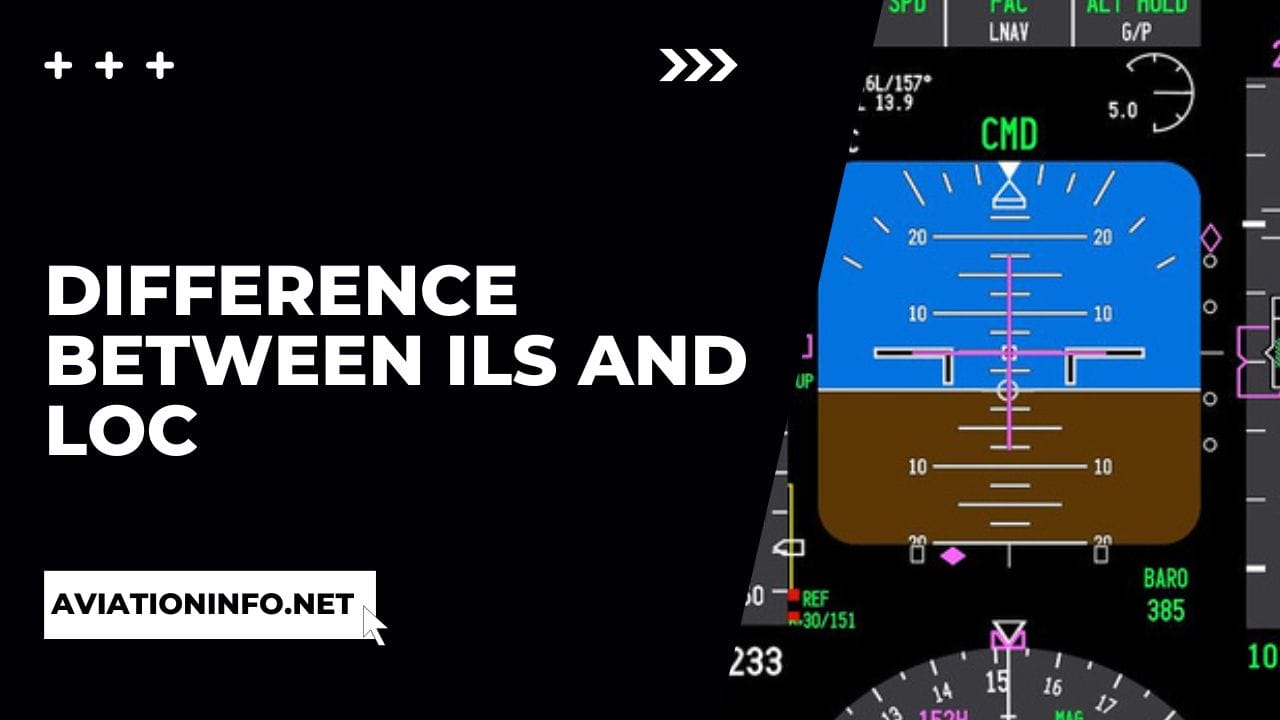
In the cockpit of modern commercial aircraft, the localizer portion is given typically on the Primary Flight Display (PFD). The lateral cues are usually displayed on the bottom half of the PFD, in a magenta-like format.
The course for the runway in which an approach is being conducted will be preselected in either the Flight Management System (FMS) and/or on the autopilot control panel under the CRS section.
As can be seen above, the lateral guidance (localizer) is being provided on the lower portion of the PFD. The hollow magenta diamond indicates the aircraft’s position in relation to the path of the localizer.
When the localizer has been captured or intercepted, this hollow magenta diamond will then become a solid magenta, as a form of confirmation.
A LOC approach may be performed in an instance where there is no ILS available for the arrival runway. However, the lack of vertical guidance to the runway in this form of approach will greatly increase the Decision Height (DH) required. This means that there are greater limitations for performing a LOC approach in poor weather conditions.
LOC approaches are rarely performed due to these limitations, ILS approaches are the preferred form of instrument approaches due to the low decision heights. This is particularly ideal when flying in low visibility conditions.
VOR/LOC
In some instances, VOR/LOC may be encountered. This typically occurs when the aircraft flies on an inbound radial of a VOR followed by subsequently intercepting the localizer. Like a LOC approach, VOR/LOC only concerns the lateral guidance of the aircraft in relation to the runway.
Essentially, the aircraft is flying the localizer via a VOR located in close proximity. Due to surrounding terrain, ATC instructions, and noise abatement procedures specific to the arrival airport, the LOC is usually intercepted and followed ahead of the Glideslope (GS).
LOC vs APPR
Upon intercepting the localizer, it is then possible to switch to Approach Mode (APPR). This is generally activated via the pertinent button located on the aircraft’s autopilot panel.
By engaging APPR mode, there is now capability for the aircraft to intercept the Glideslope (GS) component of the approach if it is an ILS approach.
Components of an ILS
There are several components that form an ILS system, each component’s respective function corresponds to a specific phase of the approach.
- Localizer – as discussed above, the LOC provides the lateral guidance to the aircraft in relation to the centreline of the runway.
- Glideslope – abbreviated as the GS, the Glideslope provides the aircraft with vertical guidance to the runway. This is typically a 3 degree gradient at most airports. However, there are also steep approaches performed at some airports (usually 5 degrees). An example of a steep approach would be London City Airport (EGLC).
- Marker Beacons – broken down into an Outer (OM), Middle (MM) and Inner Marker (IM), the ILS markers give reference points to the specific ILS approach being performed. They act as cross-references to the other components of the ILS system. They have individual aural sounds which means there is no need for the flight crew to check for visual indications.
- DME – known as Distance Measuring Equipment, the DME provides distance in Nautical Miles (Nm) in relation to the runway touchdown zone and the aircraft.
- RVR and ALS – the Runway Visual Range (RVR) and Approach Lighting System (ALS) give the flight crew visual parameters to follow in the final phases of an ILS approach. RVR is the visiblity which must be available at the specific Decision Heights (DH) for an approach. To enhance visibilty, the ALS can provide the flight crew with a clear outline of the runway.
Read More:
Difference Between SMOH, TBO, and SFOH
Difference Between VOR and NDBs

After visiting more than 60 countries, I have probably been on every type of plane there is and visited countless airports. I did my very first international solo trip to South Africa at the age of only 16 and haven’t really stopped traveling since.
Despite the adventurous travel itch, I do have a nerdy side as well – which is satisfied by writing about all things aviation “too boring” for my regular travel blog.